Showing posts with label Engine. Show all posts

29/11/2011 - Audi TT-S Engine Cover (Part 2 of 2)

As per my previous entry here, I had received my Audi TT-S engine cover and it was professionally painted by Frank in gloss white with gloss piano black inserts. I told him that he could paint the top part insert with the Audi rings and the TFSI lettering all in gloss black. Ideally, I would have liked the rings and the letters to be done in gloss white to match the engine cover but due to time constraints and with Frank having to tend to other matters regarding other customers cars I said it was okay for him to just paint it in black because I didn't want to hold him up for any work just for my engine cover. The final finish was excellent but I still wanted the rings and lettering in white. Thus, I decided to do a bit of DIY.

After a short trip to AutoBarn, I picked up a few things which I would need to complete my task. They were:

  • VHT gloss clear coat engine enamel
  • VHT gloss white engine enamel
  • K&H primer
  • 500, 800 and 1500 grit sandpaper
  • Masking tape

I chose the VHT engine enamel mainly due to the fact that it can withstand the heat created in the engine bay. According to the can, it can withstand up to 288 degrees celsius of heat and although the enamel is not meant to be applied on plastic such as the engine cover, it should be okay and should hold up. The K&H primer was the only can of primer I could find that AutoBarn had in stock. I've never heard of them before but really, any can of primer would do. This was mainly to get the enamel to stick onto the primer. The sandpaper was there to rub back the gloss black on the Audi rings and the letterings before applying the primer and to also use it after the primer was applied and dried to rub back any imperfections before applying the paint to ensure a smooth and consistent finish. 


What was purchased at AutoBarn. Engine enamel, primer, masking tape and sand paper.


The first thing to do was to mask the areas on the insert where I didn't want the paint to be applied. The large sections were okay the really difficult parts were getting in between the little spaces between the Audi rings and also the tiny spacing left by some of the letters. This took quite a long time but I wanted to do it right. Remember, your final result is only as good as your prep work. I used scissors and a small Stanley knife to cut the shapes needed to fill the strange gaps and used tweezers to apply them as this would mean that the masking tape would adhere to the surface a lot better than if I had handled them with my fingers and got my fingerprints all over the adhesive surface of the masking tape.


Preparing the insert by covering off the areas which aren't to be painted.


All masked up and ready.


Next, it was to sand back the gloss black paint on the rings and the letters. I used warm water and used the 500 grit sandpaper first. The lower the grit number on sandpaper, the coarser the sandpaper is. I tried to sand it back as much as I could and tried all sorts of ways to get into those harder to reach places on the rings and the letters. Then I used some 800 grit sandpaper to give it a smoother finish. It was now ready for primer. I applied five coats of primer, waiting ten minutes between each coat and using light coats each time with the can approximately 20-30cm away from the insert. By applying light coats, this prevents any runs and ensures a more consistent finish. I let it rest for two day before I started to sand back the primer to make it ready for paint.


Five coats of primer and sanded back for a smooth surface for the paint to stick.


Then it was time for paint. Again, the same technique was used when applying the primer. Light coats and waiting approximately ten minutes between each coat. I had applied five coats and one medium coat of gloss white engine enamel and let it cure for another two days before working on it again. Finally I applied three light coats and one medium coat of gloss clear enamel to bring out the shine. Again, I let it rest for two full days before handling. 


Five light coats + one medium coat of gloss white.
Three light coats + one medium coat of gloss clear.


Now this next part was the hard part. Because the paint was now applied over the area, the whole paintjob was one smooth finish. I was scared that if I peeled back the masking tape, it would also peel away at the Audi rings and the TFSI logo. To ensure that didn't happen, I got my small Stanley knife and carefully cut around the edges of the rings and the letterings. This process alone took about 30 minutes because it needed to be done carefully, otherwise the paint will just peel off the rings and the lettering and all that work will have been for nothing. Once it was cut, I would then use a tweezer to peel back the masking tape and also to get rid of any other remaining masking tape residue in those hard to reach places. 


Peeling away the masking tape. You can see the Stanley knife I had to use to cut around the rings and letters.


I cleaned up the residue left on the rings and cut away at imperfections around the rings and letters and here is the final result.


Result. Looks pretty good for a DIY job if I do say so myself!


What the engine cover looks like now. Success!


This whole exercise took just under a week but all in all, it turned out a lot better than I expected. Preparing the engine cover for the primer and paint was the more time consuming but the end results speak for itself. The white from the enamel is only a touch "brighter" than the gloss white of the engine cover but thats only if you go up real close and inspect it. From normal distance though, it looks fantastic and to me, it now looks complete. I will be testing the mounting points soon to see if the engine cover can fit nicely over the oil catch can hoses I have without fouling anything. If it doesn't sit nicely, then I will need to cut a section off the front portion of the engine cover to accomodate the hoses but hope it doesn't have to come to that. Will update again with photos once the engine cover is sitting nice and snug in the engine bay.

10/11/2011 - Audi TT-S Engine Cover (Part 1 of 2)

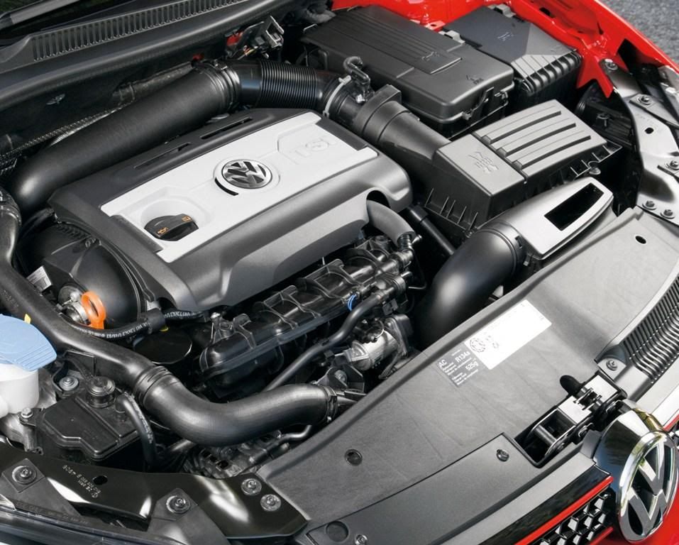
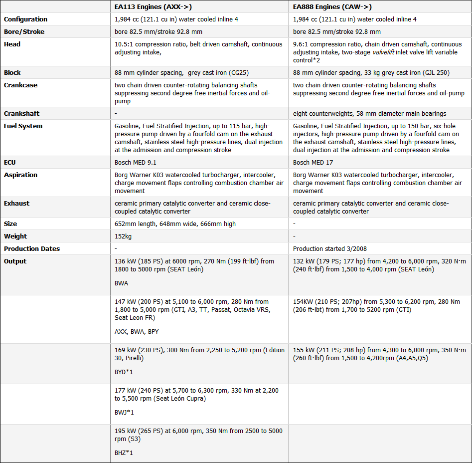
The Golf R engine cover acts as both an engine cover and a housing for the OEM air filter. It is exactly the same design as the the MKV GTI/Pirelli and the Audi S3 as they all use the EA113 engine. This engine was replaced when the MKVI Golf GTI came out with the EA888 engine. It did away with the horrible design of the engine cover/air filter integration and separated it as it should have been from the start. The MKVI Golf GTI with the EA888 TSI engine also had other upgrades too that the MKV Golf GTI with the EA113 engine did not have such as a timing chain, better fuel pump and a lower compression ratio.


EA113 engine in a MKV Golf GTI Pirelli. The air intake and the engine cover are all integrated.


EA888 engine bay in the MKVI Golf GTI. Notice how the actual engine cover and the OEM air intake are separate.


A MKV GTI to MKVI GTI comparison of the EA113 and the EA888 engine.


When I replaced the OEM air filter with the VW Racing cold air intake, it also removed the OEM engine cover. That's all well and good because some people like having the engine block exposed and it does away with unnecessary plastic that may be cluttering up the engine bay. However, I wanted to keep the engine bay looking as OEM as possible even though I had installed a cold air intake. So I started to look at what was available for the Golf R. Since the engine block was pretty much the same as the MKV Golf GTI's, whatever options there were for an engine cover for a MK5 GTI would also fit my Golf R as well as the option of cutting the original engine cover down to fit. I came across a few options...


Evolution Motorsports (EVOMS) engine cover. Not a fan of this to be honest.


Neuspeed carbon fibre engine cover. Not bad, but it doesn't cover the whole engine block.


This engine bay belongs to John who owns a beautifully modded MKV Golf GTI in black.
He is a perfectionist and this is his original engine cover which he modded and cut to fit.
The OSIR carbon fibre engine bay trim (now discontinued) goes very nicely with his Forge TWINtake.
Looks very nice and very original too but I didn't like the fact I had to hack my original engine cover.


I then came across a MKVI Golf GTI engine bay which had an Audi engine cover. Instantly I liked it and I found out later on that it came from the MKII Audi 8J TT-S and found out further that the TT-S used the same engine as the Golf R/S3 but it had a slightly different engine bay setup. The battery for the TT-S was in the boot like the MKV R32's and where the battery would normally be in the engine bay, it has an OEM intake and air filter setup. 


Audi TT-S engine cover in the engine bay of a MKVI Golf GTI.


Audi TT-S engine bay. Notice the air intake location is where the battery would normally be in the Golf R.


After doing a bit more research, I realised that you need four parts in total to get the cover to work in the Golf R engine bay. They are: 

  • 1x Audi TT-S engine cover : Part# 06F 103 925 J
  • 2x ball screws : Part# WHT 000 731 A
  • 1x ball joint : Part# 06E 103 164 E

Armed with this knowledge, I went to the service and spare parts centre at Audi Five Dock to order these in. I decided I should give them the part number because they may get it wrong and may not know the exact part I am after. Plus, it will save them the trouble and will get it right the first time around. Or so I thought. Seriously, I don't think I'll be going back to them ever again, nor would I recommend them to anyone because to cut a long story short, I waited about six weeks after I ordered as it was being shipped from Germany and I initially ended up with the wrong engine cover which was designed for a MKI Audi TT, not the MKII 8J Audi TT-S I requested. Another three week wait and I finally have the correct part. How they got that wrong even when I gave them the damn part numbers I have no idea. Eventually, after going back and forth, I got the engine cover in the end and for my troubles, they gave me the ball joint screws for free. Nice, but still wouldn't go back there for any parts. 


After more than one month, I finally had this in my possession.


I did a quick trial by placing the engine cover over the block to see what it would look like. I was very happy at this point and had completely forgot that I waited over two months to have this. 


The finishing touch.


As you can see, the engine cover comes in standard silver and are accented by matte black pieces. I promptly headed over to see Frank at Dural Prestige Smash Repair to get these painted in candy white with gloss black inserts so that it will match the fuse box and battery cover he did for me. He was quite busy with customers and there was a backlog of cars that he needed to tend to first before he could do my little trivial paint work on my engine cover. I dropped it off last week, received it today. The outcome :


Engine cover in gloss candy white, accent pieces in gloss piano black.


Close up of the engine cover.


Close up of the two accents.


I placed it over the engine block again to see what it would look like now and I must say, it does complete the look. 


Result!


The engine cover is not yet mounted due to two things that I need to address first :
  1. Now that I am running the two hydraulic hoses from the PCV plate to the oil catch can, this may become a hindrance when trying to bolt down the engine cover. I may need to use a hacksaw or something to cut a little off the front the engine cover so that it acts as an opening for the catch can hoses to route to.

  2. Since Frank and his boys were so busy doing repairs etc, I told them they could just spray the top part which had the Audi rings and the "TFSI" letters all in gloss black. But I actually want them done in white to match the engine cover. It will be a DIY rattlecan job and though it may sound dodgy, I'll be doing everything I can to make sure it's prepped and painted properly. I will need to do all the masking to make sure no residue white paint goes anywhere on the black except for the Audi rings and the letters. I'm going to be taking my time with this and will most likely sanding the black back and then applying a layer of primer, then a few coats of VHT gloss white engine bay enamel finishing off with a layer or two of clear. Not sure how well it will stick but I'm going to try and make it work. Will write a post on here when I do it and when it is properly mounted in the engine bay. Very excited and can't wait to start!

If you are involved in an accident or are looking for a quality smash repairer (NRMA approved), please contact :

Dural Prestige Smash Repair
(02) 9651 6100

01/11/2011 - Hydraulic Hose for Oil Catch Can

In my previous entry, I stated that Chris had donated his heater hoses to connect my 42DD oil catch can during the DIY day at his house as the hoses I had purchased previously were not flexible enough to be routed safely away from moving parts in the engine bay (namely the radiator fan). Because heater hoses aren't really meant for this sort of application, they eventually corrode and you would have to purchase a replacement hose. The good thing with heater hoses is that they are very cheap and are available from just about anywhere. Repco, Super Cheap Auto, Autobarn, etc. According to a few different people, they last anywhere between one to two years before they need replacing.

I had decided that I would purchase some proper hoses which would not require replacing and would last me a lifetime. I wanted to change the hoses anyway because one of the hoses leading up to the catch can was not routed to my liking. Ideally, I would have liked to have purchased some 19mm silicone hoses but I was having a lot of difficulty regarding the availability of these locally and based on my previous purchase, those hoses weren't flexible enough. I have to thank Mark from the VWG forums as he pointed me in the right direction regarding what hoses I should purchase. He had stated that he went to Enzed and purchased 2 metres of hydraulic hose, rated to 300 PSI for his catch can fitment. Enzed are the Australian arm of Parker Hannifin who are manufacturers of hydraulic hoses and fittings produced to the highest world recognised standards of SAE (Society of Automotive Engineers) and DIN (Deutsches Institut für Normung) specifications. Enzed have all sort of hoses and fittings for virtually any application. The hydraulic hoses Mark purchased were 19mm inner diameter (I/D). I went to Enzed and purchased 3 metres of the hose, just in case I cut a hose too short or made any mistakes. It's not cheap though. Heater hoses are a few dollars per metre. The Parker 300 PSI hydraulic hose was just under $30.00 per metre. Not cheap, but the quality of the hose means it will last virtually forever.


Hydraulic hose purchased from Enzed. 3 metres worth.


300 PSI rated, 19mm I/D.


Taking off the heater hoses, I decided to first empty out whatever gunk the catch can had collected since I had installed it at approximately 13,500kms before I went and actually measuring and cutting up the hydraulic hose for fitment. The Golf R is currently sitting at 16,729kms and this is the result from the oil catch can.


What came out of my oil catch can after approximately 3,000kms of driving.


Re-fitting and cutting the hydraulic hose to fit was a right pain in the ass. Making sure that the hose was routed the way I wanted it to go was proving to be a difficult exercise. I didn't want it to rub against any major components inside the engine bay. Getting the hydraulic hose on was another challenge. I had to soak the ends of the hydraulic hose in boiling water for a few minutes to soften up the hose ends and apply silicone spray to the nipples of the catch can and also the PCV plate to fit the hose over it. Eventually, after about an hour, it was all fitted back up and the whole procedure went quite smoothly.


42DD oil catch can with mounting bracket. Yes, the bracket is meant to slant like that.


The heater hoses given to me by Chris. Going to put them in storage in case I ever need them again.


Silicone spray used to get the hoses to fit over the PCV plate and oil catch can.


Before. Notice the right heater hose bending and kinking. It did the job but I wasn't happy with how it was routed.


After. Much better and the hose routing is much neater. Plus, no need to replace these hoses ever.


If you need to purchase hoses and fittings for a specific application, vehicles, machinery etc, please visit :

Enzed

21/10/2011 - DEFI Boost Gauge

A boost gauge will tell you how much pressure your turbo is creating in your intake manifold. A piston engine works by creating a vacuum in the intake to draw in more air. A naturally aspirated (NA) car can only draw in as much air as there is pressure outside of the vacuum it creates. For instance, there is one atmosphere of pressure on the outside of your intake, and on the inside once it reaches one atmosphere of pressure there will be no pressure difference to cause movement of air. A turbocharger spins a turbine driven by exhaust gases from your engine in order to force air into your cars intake. The more air you get, the more gas you can combust and the more power you can make. What a boost gauge does is tell you how much pressure is being generated in your intake manifold. It's also beneficial to have a boost gauge as this will show you if your turbo has a leak and isn't allowing it to make as much pressure or if it's set up wrong creating too much pressure, which could damage critical components.

There are a few different kinds of boost gauges as well, mainly by the way that they measure pressure. For instance, you can have a boost gauge that will measure in 'Bar' or 'PSI'. 1.0 Bar is equal to one atmosphere or 14.7 PSI, which is basically the limit an NA car can make at wide open throttle (WOT). On most boost gauges, 0 is one atmosphere of pressure, i.e what you feel on your body at all times. This is to show that you've got the same pressure in your intake manifold as there is on the air outside of it. Anything above 0 is how much boost or increased pressure above one atmosphere you are making. However, there is also another half to the gauge called a vacuum gauge. This shows the deficit of pressure in your intake manifold when it is below one atmosphere. This is what causes the engine to pull air in to it by creating a space with less air than outside the intake manifold. Vacuum is measured in inches of mercury (inHg) or millimetres of mercury (mmHg). These two gauges are generally in one, and display vacuum first then boost. Using this combination you can tell if your engine and your turbo are running correctly. Each car is different, however most will make approximately 20 inHg at idle, give or take.

I contacted JDMYard and I purchased a DEFI 2.0 bar boost gauge from their new Advance BF series, which supercedes the old DEFI-Link BF series. You can choose between a red face for the dials or a white face. I decided to go with a white face to match the white dials on my dash. It would have been nice if the needle came in blue as well to match the Golf R blue needles and I had initially thought about ripping the gauge open and painting the needle in blue to suit. However, this would void my warranty on the gauge and it would have been a redundant exercise anyway, as the LED light which lights the needle is also red in colour. So that meant if I wanted a blue needle, I would have to not only paint the needle blue, but find a blue LED to solder onto the DEFI gauge circuit board. Too much trouble and too many things can go wrong so I scrapped that idea.

I had always loved the DEFI gauges as the quality of the gauges are second to none and I love the fact that when the car is turned off, the face blacks out as well, revealing nothing on the gauge. The numbers and the needle on the gauge only turn on when the car is on. It also has a cool start up and shut down ceremony too, like the gauge sweep that the Golf R needles do when you turn the car on. The DEFI gauges however shows the vacuum in kilopascals (kPa) x100 rather than inHg. 1 kPa is approximately 0.30 inHg, so when my Golf R is idle, I should be expecting about 60-80 kPa, which is 18-24 inHg for the vacuum. The DEFI gauges are electrical gauges and they use a control unit to get the gauges to work. The DEFI Advance system allows gauges and displays to be attached to the Advance control unit with a single "daisy chain" wiring system. The system is also designed to allow all sensors to be attached to the Advance control unit so that gauges and displays can be mounted separately without the need for multiple tubing or wiring to each gauge. This is great for when you want to run multiple gauges such as oil pressure, oil temp, water temp, exhaust gas temp, fuel pressure etc.


Diagram showing the DEFI daisy chain using the control unit.
The Advance CR is DEFI's 52mm gauge range and the Advance ZD is the DEFI's LED display unit.


DEFI Advance CR Series gauges on Justin's MKV GTI. You can see the DEFI Advance controller behind the wiper stalk.


The Advance BF series gauges are all 60mm gauges, and I needed a place to mount them. I didn't want to screw any holes on the dash or anything like that, nor did I want to use the supplied gauge cup holder and double stick tape the holder down. OSIR had released their O-Pod Mono gauge holder, which replaces the driver side air-con vent with a gauge pod holder designed for both a 52mm gauge and a 60mm gauge. I purchased this from Ian at Rennenhaus and then promptly dropped it off to Frank at Dural Prestige Smash Repairs to get the pod painted in gloss black to match the rest of my gloss black trim. Once I got it back from him, I test fitted the boost gauge.


OSIR O-Pod Mono gauge holder, painted in piano gloss black.
DEFI Advance BF 2.0 bar boost gauge with DEFI Advance control unit.
Notice how the gauge face is black. This will light up when the car is on.


Initially, I tried to DIY this myself but because this was an electrical boost gauge, I had to hook up the Advance control unit so that it turned on only when the car was turned on, otherwise it would drain the battery. However, I didn't have a multi-meter or anything of that nature and as I stated in one of my previous posts, I'm clueless when it comes to all things electrical. So, I headed on down to see Dedy at Top One Automotive to get him to install it for me. Dedy is another mechanic who I can trust regarding any installs that need to be done to my car. He had previously installed my H&R front and rear sway bars and KW V3 coilovers on my old Jetta before the car got written off. He had also installed Justin's DEFI gauges as well as installing Christina's air suspension on her R32. He is a car lover and enthusiast as well and won't charge you an arm and a leg for anything. Top quality work every time and an all round great guy.


Top One always has some fancy cars being modified. Everything from simple coilover installs to race prep for time attacks.


Engine cooling off before commencing work.


Top One recently moved locations and although it was only a few hundred metres from the old location, it's at least three times bigger, which is good!


Dedy getting busy.


In order to get the gauge working, you need to connect a vaccum line to the boost tap.


Close up of the boost tap.


Wiring everything up.


While waiting for the boost gauge to be fitted, I saw Dedy's ride parked outside the workshop. He drives the only genuine FD2R Honda Civic Type R in Australia which he personally imported from Japan, meaning it was a yellow plate import. Apart from his, I don't think there is another FD2R in Australia. Like the Golf R's, GTI's and R32's, it's a very unassuming car as it looks like every other Honda Civic out there on the road, minus the rear spoiler. However, I'll bet that his car can be quite an animal when it wants to be.


Dedy's Honda Civic Type R (FD2R) in Championship White.


A car worthy of the Type R badge.


FEEL's titanium catback. My fist could fit through the exhaust! Crazy!


Standard FD2R Brembo brakes behind AME Tracer TM-02 wheels. Very similar design to the Enkei RPF1.


Dedy finished up the wiring and the DEFI boost gauge was now installed. The control unit was hidden away behind the spare compartment just under the driver side air-con vent and the boost gauge was now snug fit into the OSIR O-Pod Mono gauge pod holder and located where the driver side air-con vent used to be. Clean install and again, always happy with his work.


Boost gauge installed! Notice that it idles at approximately 0.7x100 = 70 kPa, which is about 21 inHg, which is spot on.


Video of the boost gauge in action installed on my Golf R. The startup and shutdown ceremony is pretty neat!


If you would like to purchase the items above and go to a reputable place to install your mods, please visit : 

Top One Automotive

JDMYard

Rennenhaus

03/09/2011 - VW Racing Cold Air Intake + 42DD Oil Catch Can Install

There is a large debate as to whether or not oil catch cans are worth the money or not. Personally, I think an oil catch can is very beneficial, especially for direct injection engines like on the Golf GTI and Golf R.

First, let's go over what is currently happening in your engine without a catch can installed. All internal combustion engines that run off gasoline are 4 stroke engines. This means that the piston has to go up and down a total of 4 times to complete a cycle. The piston first goes down with the intake valves open creating a vacuum. This draws in the cool dense air for combustion. At the same time, fuel is injected into the cylinder. The intake valves close and then the piston rises up towards the top of the cylinder. This compression creates an immense build-up of pressure in the cylinder. The only things containing this high pressure are the cylinder itself, the piston and the piston rings that seat against the walls of the cylinder. The intake and exhaust valves are obviously closed as well. The pressure is so high that a very small amount of the air escapes around the piston and piston rings into the crankcase. This is called "blow-by". The amount of blow-by increases as the engine RPMs rise. Also, an engine with more cylinders will have more blow-by. Obviously not all of the air escapes or else combustion wouldn't take place. A diagram of the 4-stroke cycle can be seen below. Only the first 2 steps are relevant in regards to the catch can.


Inside the crankcase, you have the crank which is turning in the oil pan which is full of oil. This keeps it properly lubricated. The positive crankcase ventilation (PCV) is necessary to ensure there isn't a build up of pressure in the crankcase. This would cause the crankcase to possibly crack under the pressure and create a huge mess of oil on the street. So the PCV system removes the pressure from the crankcase and reverts it back through the intake tract via crank case vents. This pressure isn't made up of 100% air. It will also contain a very small amount of oil as well since there is so much in the oil pan at a high temperature. This air and oil mixture is then entered somewhere after the intake system, passes through the intercooler (if you car is turbo or supercharged) and then re-enters the combustion chamber (cylinder) through your intake valves to be re-burned. The oil will actually coat everything on its way back to the combustion chamber. It will develop in the intercooler, boost hoses, intake manifold and intake valves. Just on the other side of these valves is where the combustion is taking place where the temperatures are extremely high. This is what actually causes the oil to solidify on the valves. With the oil passing through the intercooler, it can actually coat the cooling fins which will hinder the intercooler's ability to cool the air therefore lowering the efficiency.

The caking on intake valves is only a problem with direct injection engines. For all other engines that use port injection, the gas is introduced before the combustion chamber which means it flows over the intake valves and enter the combustion chamber premixed with the air. This action of the fuel flowing over the intake valves actually cleans the valves from any oil that make already be on there. The oil never has the chance to cake on the valves in port injection engines.

Having oil caked onto your intake valves can cause the following symptoms:
  • Knocking
  • Pre-ignition
  • Loss in power
  • Loss in fuel economy

Here is an image of carbon build-up on valves. Yes, it's nasty...


An oil catch can does just that. It catches or prevents the oil from re-entering the intake tract. A catch can is placed right after the PCV and before the intercooler. This means that a more pure (sometimes 100% pure) air mixture will go through the intercooler and intake valves. A more pure air mixture entering the intake valves means no caking and none of the symptoms listed above. Oil catch cans are highly beneficial in race applications and if you track your car. However, for my purposes, it was more of a preventative measure as I wanted the extra gunk to be collected and eventually emptied out instead of having it recirculate.

I decided to buy a 42 Draft Design catch can. Reason for this was because a forum member I had met, Chris, had purchased this catch can from Greg, who owns and runs Carformance and who is also the Australian distributor for 42 Draft Design products. Chris, who has a Golf R himself, said he would be the guinea pig and was trying to get a mounting bracket set up which could be used and sold with the catch can together, thus eliminating any need for custom work. After collaborating with Greg for a few months, the new mount was ready and I had told Greg that I would like to be one of the first to purchase it once the bracket was complete. After some initial delays, a few weeks later I had received the catch can.


42 Draft Design oil catch cans. I opted for left one with the billet top and black wrinkle finish on the can.


Prior to receiving the oil catch can, I had also ordered a cold air intake. Basically, a cold air intake is a system used to bring down the temperature of the air going into a car for the purpose of increasing the power of an internal-combustion engine. For a turbo car like the Golf R, it's an inexpensive way to increase performance. All cold air intakes operate on the principal of increasing the amount of oxygen available for combustion with fuel. Since cooler air has more density for a given volume, cold air intakes generally work by providing cooler air from outside the hot engine bay. Better designed intakes use heat shields to isolate the air filter from the rest of the engine compartment, providing cooler air from the front or side of the engine bay. VW Racing had just released their new cold air intake system for the MK6 Golf GTI's and Golf R's and I decided to purchase it. I contacted Ian from Rennenhaus as he is the official distributor for VW Racing parts, and within a few weeks I had the intake ready to install.


VW Racing cold air intake offering for the MK5 GTI, MK6 GTI and MK6 Golf R.


I contacted Chris to see if we could do a DIY with catch can seeing as how he was the one who fabricated the mount, he'd have a better idea on how to install it. I also asked if we could install the intake at the same time and he was fine with it. So I arrived at 9:30am in the morning at his place and we got stuck in. We started with the intake. Ripping off the OEM engine cover was a right pain in the ass, but luckily we didn't break anything.


Engine cover off. Intake and catch can ready to be installed.


After a few hours, we ended up installing the intake. Not as straight forward as we thought it would be and after a test drive, not as loud inside the cabin compared to when I had my Forge TWINtake on my Jetta. However, the "whoosh" sound is more apparent under load. There were some custom modifications we had to do to make it fit the Golf R. The intake itself is simple plug and play. However it seems like that this intake caters for both the K03 and K04 turbos. Those with a K03 turbo (i.e Golf GTI) should be fine but with K04 turbo, the diverter valve (DV) is at the front (compared to down towards the bottom of the car on a GTI) and the pipe from the DV runs up the side and into a bung on the hose as seen in the picture below. You have to create a hole on the silicone pipe to accomodate for the DV bung. To be honest, VW Racing's method to cut a hole on that silicone pipe is a piece of shit really. They give you a "cutter", which is just a small hollow cylinder and what they want you to do is to line that cylinder inside the silicone tube, put a block of wood inside the tube tube so that the cylinder presses up against the pipe from the inside, place it on a flat surface and smash it using a rubber mallet. Pretty ghetto for an intake which cost as much as it did.


VW Racing instructions on how to fit the DV bung to the silicone pipe. Pretty pathetic to be honest.


Problem with this method you do not know if the cutter is in the right place because essentially what you're doing is taking an estimate and an educated guess as to where the bung "should" go. You'd be basically hitting with the mallet and hoping for the best. Not only that, the block of wood needs to sit on the bit of the pipe which bends. Plus, really, for the DIY'er, who has a small block of wood like that lying around? It really is a bullshit design. So instead, Chris took the disconnected DV tube and then loose fitted the silicone pipe onto the turbo, then got the DV tube and placed it where it would be optimal, traced around the circumference of the DV tubee against the silicone pipe, used a drill and a wood bit to drill into the pipe, cleaned the edges with a small stanley knife and attached the bung applied with some Loctite to make sure it stays in place. Apart from that, no real issues in fitting the intake. If you have a GTI, it should be just a case of taking the engine cover and old intake off and putting this one on. For the Golf R, GTI Pirelli or the GTI Edition 35, you would need to create that hole in the silicone pipe.


A much more accurate way of cutting the hole for the DV bung in the silicone pipe : A drill with wood bit and a Stanley knife to clean around the edges. Perfect!


Intake installed. Notice how the DV tube lines up nice and straight connecting to the silicone pipe. 
Would have been near impossible with the method VW Racing provided.


I had also bought two 1 metre long silicone hoses for the oil catch can as theoretically, it should last indefinitely and not have the excess oil eat away at the pipe. However, when Chris was cutting bits off the hose pipe and trying work out how to feed the pipes to the catch can, the problem we ran into was that the actual silicone hose itself wasn't flexible enough and when we ran both hoses together under the air duct of the intake, it came dangerously close to hitting the radiator fan. Since the hoses weren't as flexible, it was hard to place it somewhere which wouldn't make it a problem and away from any moving objects in the engine bay. In the end, we gave up trying to come up with a solution because there really wasn't one. But I still needed a way to drive and get home, so Chris offered to give me his hoses he had on his Golf R, which were just normal heater hoses you can get from Super Cheap Auto. And because the hoses I bought were of no use anymore (not to me anyway), I said he could hang onto them so he could experiment with them for whatever. Heater hoses are cost effective, but they aren't really designed for oil and if unattended for a a few years, it can corrode and eat away at the hose and you will end up having crap all over your engine bay. It should last at least a year for my application and for now it will do the job fine. Eventually, I will be going to Enzed real soon to buy proper 19mm hydraulic hoses, which should theoretically last forever.


Oil catch can installed. Notice the route of the right heater hose to the oil catch can.
This is not the most optimal place to route a heater hose to the catch can but it will work as a temporary measure.
Ideally, I would like to have both pipes running in the same direction as the hose on the left and keep them together with a zip tie.


All in all, it was a successful day out and massive thanks to Chris for helping me with the DIY. If it wasn't for him, I wouldn't have been able to get through installing this as quick as we did and I would also be stuck with those silicone hoses.


If you would like to purchase these items as well as many other mods which may be available for your Golf GTI or Golf R, please visit :

Rennenhaus
http://www.rennenhaus.com.au

Carformance
http://www.carformance.com.au